
Does the battery inexplicably discharge even though all devices are disconnected via their switches? O r have we detected corrosion on the propeller shaft, making us suspect stray currents generated by a poorly insulated system? Let’s see how to detect any current leakage in our onboard system.
A Brief Introduction
For current to flow, the electrical circuit must be closed. It starts from one battery terminal and ends at the other. Let’s take the car radio power circuit as an example: if we start from the positive terminal of the battery and follow the red power cable, we will most likely reach the switch on the boat’s panel, from there it will go to a fuse and then to the positive terminal of the car radio. We will proceed from the negative terminal of the car radio with a black cable to finally end at the negative terminal of the battery. The scheme will be the same for every device, such as the interior lights or the navigation lights of our boat.
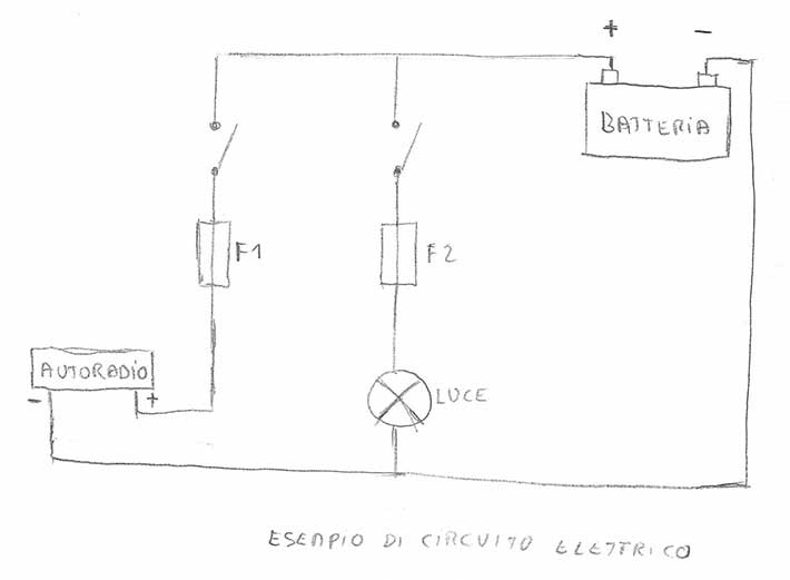
There are two other aspects to consider:
- the boat’s engine, the keel, and other metal parts are generally grounded, connected to the negative terminal of the battery.
- Saltwater has good electrical conductivity
Attention: the indications in this article are generic and informative. Each system may have its particular characteristics. An example is boats that comply with American ABYC standards, which must have bonding, while in Europe it is not mandatory.
How to Detect Current Leakage
Let’s see how to detect current leakage with a multimeter, a tool that should always be on board a boat. Disconnect the black cable from the negative terminal of the battery and insert the multimeter between the negative cable and the negative terminal of the battery.
Initially set the multimeter to A and not to mA, because if there are higher currents, they could blow the internal fuse or damage the device.
At this point, make sure all devices are turned off via their respective switches and check if the ammeter indicates a current draw. If the draw is in the order of mA, change the multimeter selector to mA for a more precise reading.
Now we need to proceed by elimination, so we will remove the fuses of the various devices one by one, physically interrupting our circuit as we saw before. Someone might say, “but we have already turned off all the switches!”: true, but who says a switch doesn’t have a defect and remains partially closed, allowing current to pass?
Continuing with our analysis, if removing a specific fuse causes the current draw to go to 0 mA, we will have identified which electrical circuit the current leakage occurs on. In this case, it is necessary to investigate further and understand where the problem lies, whether on the connected device, the switch, etc.
And if once all the Fuses are Removed, the Leakage is Still Present?
If the current draw is still present, check if there are devices connected directly to the batteries without switches, such as automatic bilge pumps.
It is therefore necessary to identify the devices connected directly to the battery and isolate them one by one, disconnecting the power cables individually. This involves working with and touching the electrical system, so
There is also the alternator that could generate leaks if it has a broken diode bridge: try disconnecting it and see if the current leakage is still present.
Stray Currents and Corrosion
Imagine that the wiring of the navigation light on the bow pulpit is poorly insulated and in contact with the metal part. Apparently, on a fiberglass boat, it doesn’t seem to be a big problem, as the metal structure remains isolated. In reality, it’s not quite like that: when the boat gets wet with seawater, the latter will create an alternative path, closing our circuit by passing, for example, through the keel or the propeller shaft which are grounded.
Apart from the anomalies that would manifest on the device affected by poor wiring insulation, the major problem will be the stray current that would be generated and lead to corrosion of the anodic part, in our case the stripped cable and the pulpit.
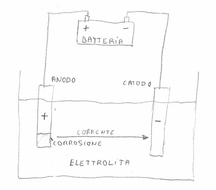
We are facing an electrolytic cell, which, unlike a galvanic cell (battery), oxidation is forced by removing electrons from the anode through a current generator (boat battery).
Compared to a galvanic current, the stray current has a higher current intensity and therefore leads to more significant, rapid, and marked anode corrosion. It should also be noted that a stray current is generated by an imposed electrical potential and can occur even between two identical metals.
As seen in the diagram below, the metal that leaks current into the electrolyte is indeed the anode connected to the positive terminal.
Even solar panels and wind turbines can present this type of problem as they are normally mounted on metal structures, such as pulpits or roll bars.
Other Examples of Stray Currents and Corrosion
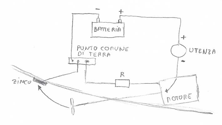
Let’s look at the case of corrosion of a propeller and its shaft.
We have an electrical component that has its return connected to the engine ground. The propeller and shaft are also grounded with the engine. The engine is then connected to the negative of the battery through a common ground point. At a certain point, a defect occurs on the return path between the engine and battery, such as contact oxidation that would cause some resistance to the current (in the diagram R). The current will clearly choose the easiest path, in this case passing through the shaft – seawater – zinc to then reach the battery.
Another real example is the bilge pump: if one of the power cables were poorly insulated, it would come into contact with the water in the bilge, and the current would find another return path to the battery through the keel bolts, propeller shaft, or engine that are grounded.
In this case, the switch would suffer corrosion and would no longer start the pump when needed, resulting in flooding or sinking of the boat.
How to Detect a Stray Current
To detect a stray current, turn on all devices.
Set the multimeter to the Voltmeter function. Connect the black cable to the negative terminal of the battery, possibly using a very long cable. This will allow us to move around the boat and measure any abnormal voltages on the (wet) hull or on metal elements where cables pass inside (such as pulpits). If a voltage of a few volts is measured, disconnect the battery and see if it disappears. If so, we have found a current leakage and a probable stray current.
How to Protect against Stray Currents and the Corrosion They Cause
We have previously seen that it is the direction of the flow of a stray current that determines which metal is subject to corrosion. Additionally, stray currents can also occur between identical metals, so it is easily deducible that zincs do not prevent the formation of this type of corrosion caused by stray currents.
Good protection against stray currents is provided by expertly executed wiring, without leaks, defects, and false contacts. Each device must have its negative cable of the same diameter as the positive and must return directly to the negative of the battery, passing through the single common ground point. For the return
Note: stray currents should not be confused with galvanic currents, which are instead generated by natural phenomena and have much lower current intensity. But this is a complex topic that requires separate in-depth study.
Battery Handling
It is a good rule that when you want to change or simply disconnect the battery, you start first with the negative terminal and then the positive terminal.
Why? Normally, metal parts, particularly the cases of electronic devices, are grounded. Think, for example, of a battery charger with a nice aluminum case placed near our battery. We start unscrewing the positive terminal clamp with a wrench and inadvertently touch the battery charger’s case. We will have a short circuit, where we risk getting hurt and will probably cause the device to break.
If instead, we start disconnecting the negative terminal clamp, this cannot happen.
Documentation on the Subject
You can find everything and more online, often reporting incorrect information.
For those who know English, I recommend a book that, in my opinion, should be on board every boat.
Boatowner’s Mechanical and Electrical Manual by Nigel Calder
See other articles related to electrical systems.
Subscribe to the blog to not miss upcoming articles!
Last update: